Optical Coherence Tomography (OCT) is an intravascular imaging modality that uses near-infrared light to provide high-definition, cross-sectional and three-dimensional images of the vessel microstructure during percutaneous coronary intervention (PCI).
"These images provide additional information on the degree and characteristics of coronary artery disease compared to angiography which doesn’t delineate the composition of the coronary artery.1 With automated, highly accurate measurements, OCT can guide stent selection, placement, and deployment.1"
— Dr. Manuel M. Reyes, Interventional Cardiologist
Ultreon™ Software is powered by artificial intelligence (AI) and automation. It has an improved and intuitive user-interface over the previous generation.*

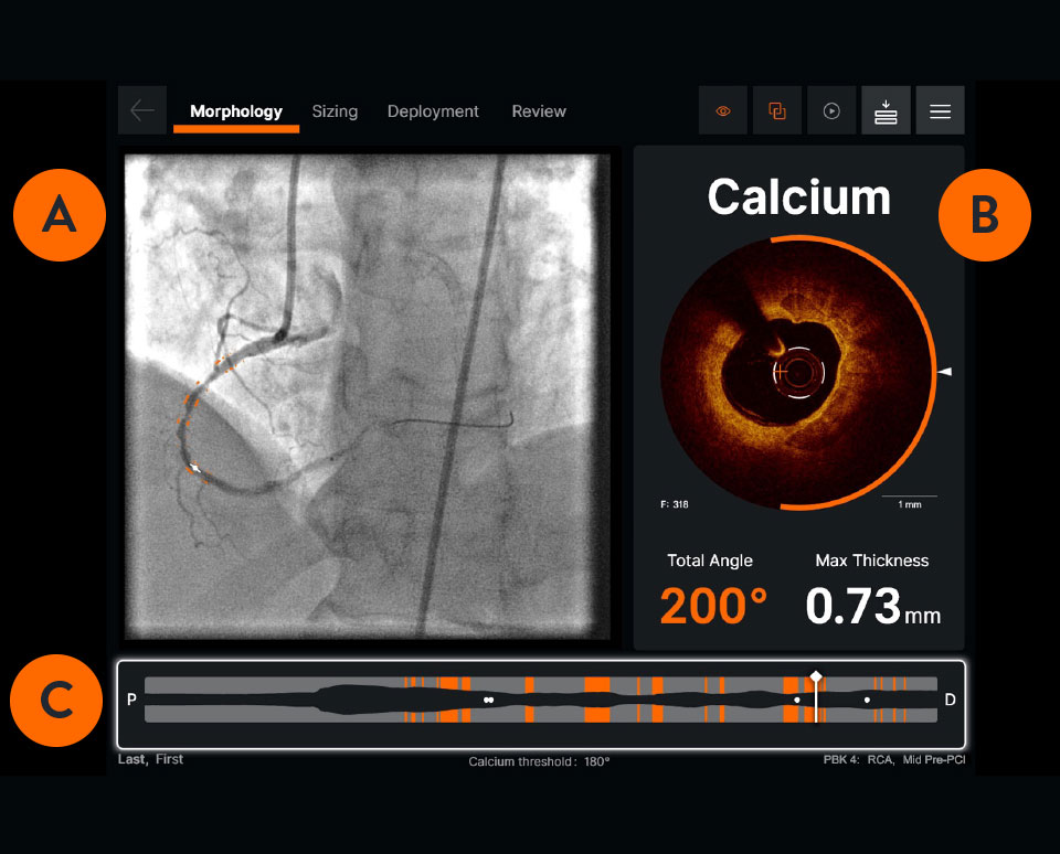
Ultreon™ 1.0 Software User Interface. Pre-PCI pullback. Automatically displays degree and max arc of calcification.

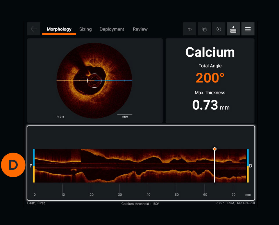
Ultreon™ 1.0 Software User Interface. Pre-PCI pullback. Automatically displays degree and max arc of calcification.

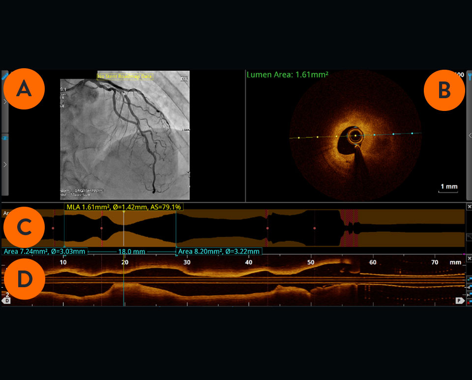
Previous generation AptiVue™ Software User Interface. Pre-PCI pullback.
Angiogram co-registration denotes location of the cross-sectional OCT image.

Cross-sectional visualization is used to obtain detailed findings, such as structures in the lumen and in the various layers of the vessel wall.

The cross-sectional area of the vessel is visualized along the entire length of the examined vessel segment. It allows precise determination of the vessel diameter (mean reference diameter) and the length of the altered segment. The white marker is located at the position of the cross-section shown.

Viewed from left to right, the longitudinal section visualizes the scanned vessel segment from proximal to distal in Ultreon™ Software, and from distal to proximal in AptiVue™ Software.

PCI guidance with OCT is easier now with the development of the standardized step-by-step workflow (also referred to as algorithm), MLD MAX, which is mnemonic for Morphology, Length, Diameter, Medial Dissection, Apposition and Xpansion. Using OCT with MLD MAX workflow can improve stent expansion4 without additional contrast while reducing radiation exposure compared to angiography-guided PCI.5 Stent expansion is linked to better PCI outcomes.6

Use of Intravascular Imaging
For references, refer to the original document.
OCT imaging systems consist of three main components: the software, the system, and the catheter.
Ultreon™ Software includes auto detection of certain components of the vessel based on artificial intelligence. The software is intended to be used only with compatible OPTIS™ Next Imaging Systems.

The hardware that runs the OCT software. OPTIS™ Systems use optical imaging catheters that emit near-infrared light to produce high-resolution real-time images. The OPTIS™ Next Imaging Systems can be integrated with the cath lab angio systems to display OCT and angio co-registration (ACR) on the same screen.

The OCT catheter is intended for the imaging of coronary arteries.

To perform an OCT pullback, an OCT catheter is inserted into the vessel and an infrared laser is used to scan the vessel wall in a spiral-like manner. The laser beam penetrates the tissue 2-3mm deep, is reflected from there and returned to the OCT device via the catheter for evaluation.7
Watch this video to learn how to set up the OCT system. These step-by-step instructions are available on the OCT screen for easy guidance.
There are four steps to an OCT-guided PCI set up:
Watch this video to learn how to initiate a pullback. The step-by-step instructions are also available on the OCT screen.
Due to the OCT systems’ high acquisition speed, images of pullback can be produced and visualized in a matter of seconds. The system provides precise information about the scanned vessel segment.7
Learn how to interpret OCT images, the basic elements of an OCT image and an algorithm for image interpretation.
Using OCT with MLD MAX workflow, the standardized step-by-step workflow, helps to guide pre- and post-PCI decisions. Use of the workflow resulted in an 88% change in treatment decisions8 compared to angiography alone without a change in contrast usage and a 10% reduction in radiation5, as shown in the LightLab Clinical Initiative.
Six letters represent six steps of the PCI goal to MAX-imize stent expansion to deliver optimal results.
Achieving optimal expansion is proven to reduce rates of major adverse cardiac events during PCI9. Proper expansion confirmed by imaging results in safety and efficacy benefits.6
Search for High Calcium1
Criteria:
>180 degrees, and
>0.5 mm thickness, and
>5 mm in length
Select Landing Zones Based on Healthy Tissue/ EEL Visualization2
Place landing zones in healthy tissue (i.e. EEL visualization)
Note: In the absence of EEL to represent healthy tissue find the largest lumen to avoid areas of TCFA or lipid pools so as to not land your stent edge in these high-risk areas3
Measure Vessel,
Stent, Balloon Diameters4
Use distal reference measurements to select stent diameter
Use distal reference measurement for distal balloons or proximal reference measurements for proximal balloons
Address Significant Dissection2
Criteria:
Dissection penetrates medial layer, and is greater than 1 quadrant arc
Address Gross Malapposition
Criteria:
Malapposition indicator shows longer than 3 mm4 of significant (≥0.3 mm from wall5) apposition
Confirm
Expansion3,6
Criteria:
≥80% acceptable,
≥90% expansion is optimal

Watch these videos to learn more about each step of the MLD MAX workflow: Morphology, Length, Diameter, Medial dissection, Apposition, and Xpansion.
What is the value of morphology-guided lesion prep?
Why does proper stent length matter?
Why does accurate diameter matter?
There are three types of dissections: intimal, medial and intramural hematoma. A dissection which penetrates the medial layer and > 1 quadrant arc needs to be treated although various recommended angles exist, including > 60 degrees.9 A simplified approach used by operators is to measure a 1 quadrant arc.
An important aspect of optimizing PCI is the detection of underexpansion after stent placement.9
*As compared to AptiVue™ Software
MAT-2113908 v3.0
Stay Connected